
Field Notes
I Built a Cloud-Shaped Noise Machine for My Daughter
My daughter is on the way, and I wanted to make her a little noise machine before she arrives. An ESP32, a speaker, a volume knob, and a little enclosure. How complicated could that be?
Well, getting it to make noise was pretty straightforward. Getting all the pieces to fit together was where things got interesting lol.
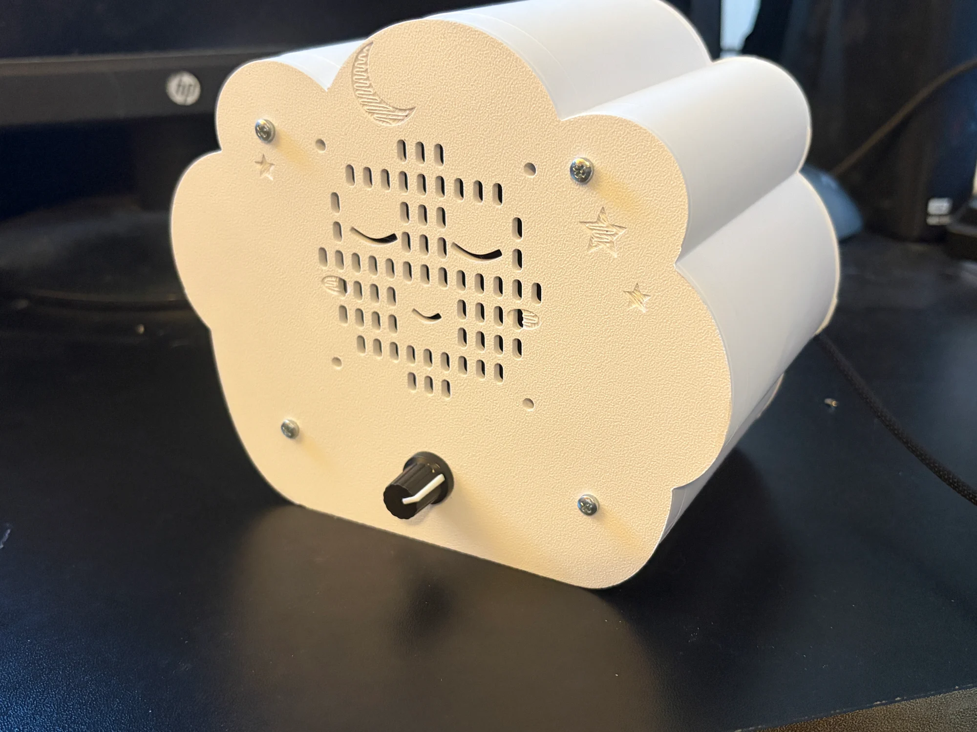
This is the current result. We ended up with a sleepy cloud, with a moon and stars on the front, a real volume knob, and USB-C power on the back. It makes white, pink, or brown noise, with optional ocean-like swells. It works and makes the sounds I wanted. Now it just needs to wait for its intended audience. I wouldn’t call the project finished forever though. I already have a couple things I want to change.
The files, before I get into the story
If you want to build one or mess around with the design:
- Complete project download: the Arduino sketch, five enclosure parts, Blender files and build scripts, wiring diagrams, assembly guide, and photos.
- Arduino code: Download esp32_pink_ocean.ino as a separate file. Put it in a folder named
esp32_pink_oceanand open it in Arduino IDE. The sketch ZIP already has that folder structure. - Just the printable parts, if that is all you need.
- Editable CAD sources and assembly notes.
- Wiring diagram and physical ESP32 pin guide.
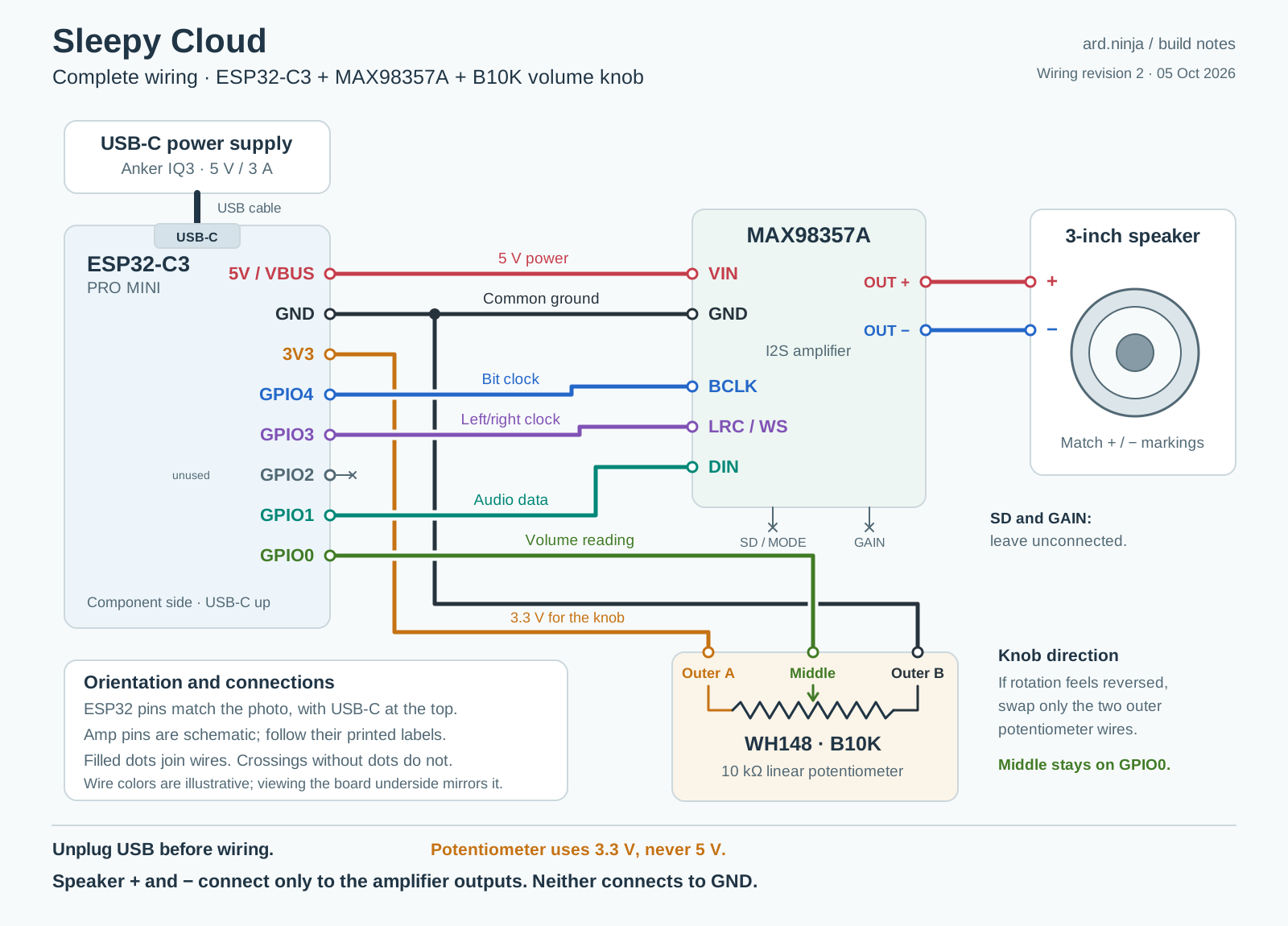
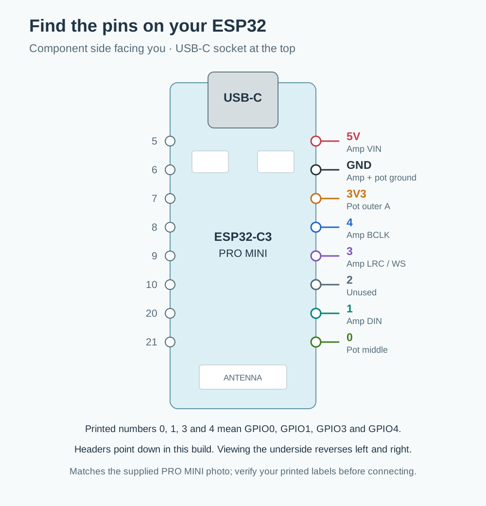
The main print set is the version used for this build. There’s also a separate reinforced ESP32 holder in the complete download. I have not printed or installed that revision yet, so don’t confuse it with the holder in these photos. More on that below.
Exactly what is in the download
The print-only ZIP contains README.md and these five STLs in its print-files folder:
- 01-shell.stl - Middle shell.
- 02-single-front-plate.stl - Front grille, speaker seat and potentiometer mount.
- 04-rear-panel.stl - Rear cover with USB opening.
- 08-pot-keeper.stl - Potentiometer retaining piece.
- 09-esp32-cradle.stl - ESP32 holder.
The optional replacement is 09-esp32-cradle-reinforced.stl. It is included in the complete ZIP, separately from the five baseline parts.
The complete ZIP also includes the code, editable models, source scripts, fit samples, diagrams and photos. Here is every file, with its path inside the sleepy-cloud folder:
Show the complete download file list
README.md
SHA256SUMS.txt
assembly/bolt-and-nut-detail.png
assembly/front-print-guide.png
assembly/front-shell-exploded.png
assembly/holder-nut-installation-guide.png
assembly/optional-holder-comparison.png
cad/esp32-cradle-reinforced-v3/09-esp32-cradle-reinforced.stl
cad/esp32-cradle-reinforced-v3/build_reinforced_cradle.py
cad/esp32-cradle-reinforced-v3/inputs/previous-cradle.stl
cad/esp32-cradle-reinforced-v3/reinforced-cradle.blend
cad/esp32-cradle-reinforced-v3/review_reinforced_cradle.py
cad/esp32-cradle-reinforced-v3/validate_stls.py
cad/sleepy-cloud-v8/01-shell.stl
cad/sleepy-cloud-v8/02-single-front-plate.stl
cad/sleepy-cloud-v8/04-rear-panel.stl
cad/sleepy-cloud-v8/08-pot-keeper.stl
cad/sleepy-cloud-v8/09-esp32-cradle.stl
cad/sleepy-cloud-v8/build_sleepy_cloud.py
cad/sleepy-cloud-v8/inputs/esp32-cradle-v2.stl
cad/sleepy-cloud-v8/inputs/mirrored-pot-plate.stl
cad/sleepy-cloud-v8/inputs/pot-keeper.stl
cad/sleepy-cloud-v8/review_assembly.py
cad/sleepy-cloud-v8/sleepy-cloud-v8.blend
cad/sleepy-cloud-v8/validate_stls.py
firmware/esp32_pink_ocean/esp32_pink_ocean.ino
fit-samples/potentiometer/01-potentiometer-capture-plate.stl
fit-samples/potentiometer/02-potentiometer-back-keeper.stl
optional-reinforced-holder/09-esp32-cradle-reinforced.stl
optional-reinforced-holder/process-5walls-40percent.json
photos/esp32-fit-test.webp
photos/finished-closeup.webp
photos/finished-front.webp
photos/finished-overhead.webp
photos/finished-rear.webp
photos/front-shell-exploded.webp
photos/header-clearance.webp
photos/inside-assembly.webp
photos/potentiometer.webp
print-files/01-shell.stl
print-files/02-single-front-plate.stl
print-files/04-rear-panel.stl
print-files/08-pot-keeper.stl
print-files/09-esp32-cradle.stl
wiring/build_diagrams.py
wiring/esp32-c3-pin-guide.png
wiring/esp32-c3-pin-guide.svg
wiring/sleepy-cloud-wiring.png
wiring/sleepy-cloud-wiring.svg
wiring/wiring-netlist.json
What went into it
Here is the simple bill of materials. The links are the listings I bought from.
| Quantity | Part |
|---|---|
| 1 | ESP32-C3 PRO MINI board |
| 1 | MAX98357A I2S amplifier module |
| 1 | 3-inch speaker, matching the 59 mm mounting-hole spacing |
| 1 | WH148 B10K linear potentiometer, 10 kΩ, plus its knob |
| 1 set | 5 V USB-C power supply and cable. Mine is an Anker IQ3 rated for 5 V / 3 A |
| 1 set | Pin headers, female jumper wires, and speaker wire |
| 1 assortment | M3 machine screws and nuts in the lengths needed for the different mounts |
| 1 set | The five printed enclosure parts listed above |
I printed the enclosure on my Bambu A1 mini. You also need a soldering iron for the headers and a USB data cable to upload the program. The assembly notes explain the mounting hardware and print settings.
The speaker listing calls it a 25 W speaker. That is the seller’s rating for the speaker, not the power this little amplifier is putting out. The listing also covers different impedance options, so check the actual part you buy.
Power comes through the ESP32’s USB-C port. Its 5 V pin supplies the amplifier. I’m using an Anker IQ3 supply rated for 5 V at up to 3 A.
I worked through this with ChatGPT and Codex, from getting the board programmed to writing the firmware and generating the Blender enclosure. I did the measuring, printing, wiring, and the very important part where you discover that the thing on the screen doesn’t actually assemble the way you thought it would.
First, make it make a sound
We started with a very quiet test tone, before doing anything clever with noise generation. That let us check the ESP32, amplifier, and speaker as a chain.
There was initially some quiet crackling when I powered it from my MacBook. Moving it to the Anker supply cleared that up. That was an observation about this setup, not a diagnosis of every MacBook USB port. It also turned out to be a separate issue from the much worse static I ran into during final assembly.
Once the tone was working, we tried white noise. Then pink noise. Then brown noise, plus a slowly changing volume envelope to get something like ocean swells.
To my ears, white noise has more hiss, pink is softer, and brown has more of a low rumble. I wanted to be able to experiment instead of committing to one sound in the code. The swells are generated by changing the noise level over time, not by looping an ocean recording.
One revision of the mode-switching program made white noise sound ragged. I went back to the earlier white-noise sketch and it sounded fine, which was a useful check. That problem really was in the program. We revised the audio generation and smoothing, and it sounded good again.
The current sketch synthesizes audio at 44.1 kHz and sends the same signal to both I2S channels. It uses short crossfades when changing noise colors and ramps volume changes. The swell cycles vary between roughly 9 and 15 seconds. The pink filter is based on Paul Kellet’s pink-noise work.
No audio files or network connection are needed for playback.
Wiring and controls
Here is the complete wiring diagram. We corrected the ESP32 drawing to follow the physical pin order on my board, because an electrically correct diagram is still annoying if the pins are drawn in a different order than the thing in your hand.
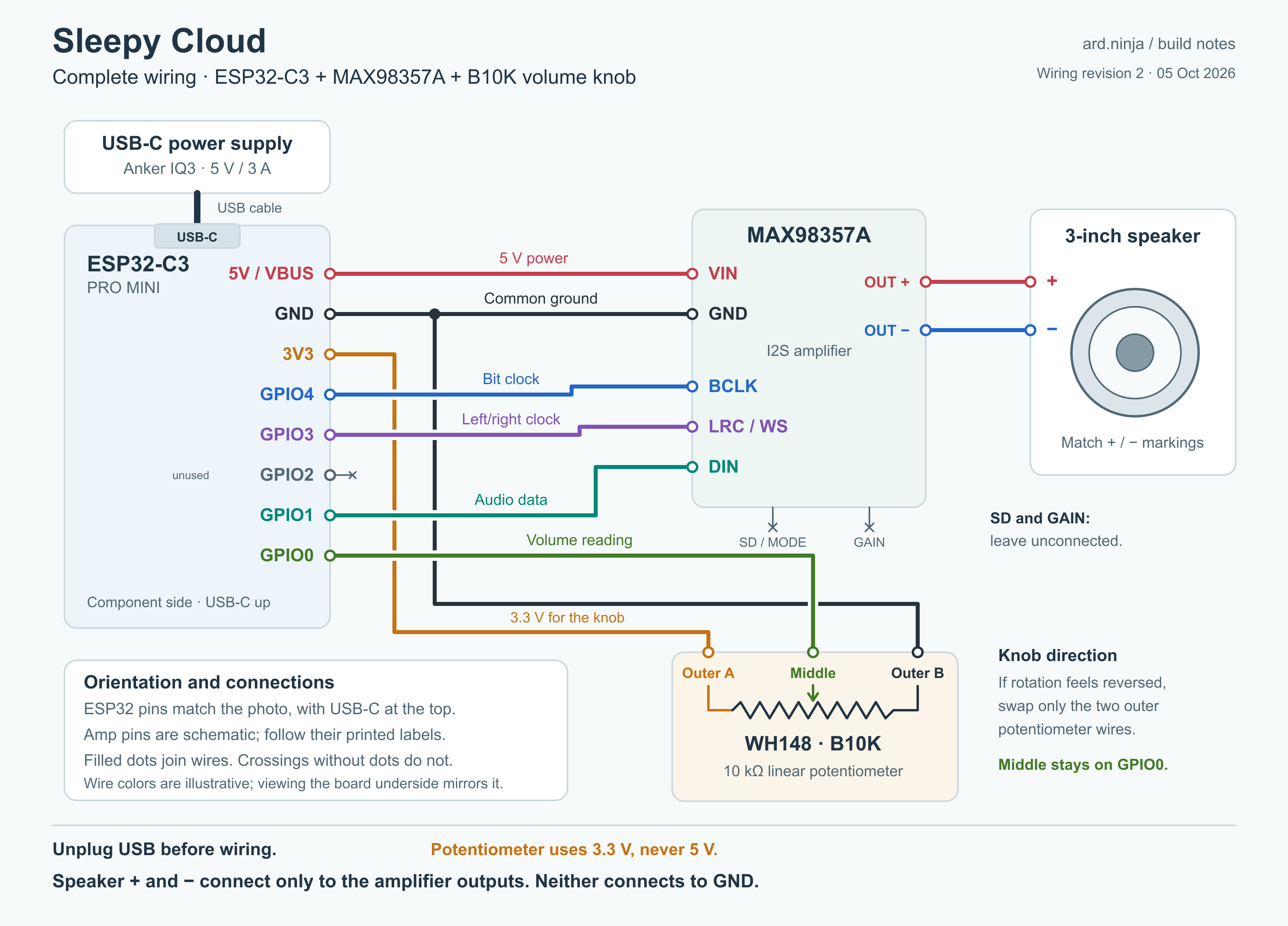 Click to enlarge. The amplifier block is schematic: follow the labels on your actual module. The separate pin guide shows the ESP32 from both sides.
| ESP32 connection | Destination |
|---|---|
| 5V | Amplifier VIN |
| GND | Amplifier GND and one outside potentiometer terminal |
| 3V3 | The other outside potentiometer terminal |
| GPIO0 | Potentiometer middle terminal |
| GPIO4 | Amplifier BCLK |
| GPIO3 | Amplifier LRC / WS |
| GPIO1 | Amplifier DIN |
The speaker goes between the amplifier’s two speaker outputs. Neither speaker wire goes to GND. SD and GAIN are both left unconnected on my amplifier module. The MAX98357A pinout guide explains those connections.
For programming, I used Arduino IDE with Espressif’s ESP32 board package, version 3.3.12, selected ESP32C3 Dev Module, and enabled USB CDC On Boot. Install the board package using Espressif’s instructions, open the downloaded sketch, and select the port that appears for your connected board. The sketch uses the package’s ESP_I2S library.
The physical knob controls volume. Mode changes currently happen through Arduino’s Serial Monitor at 115200 baud:
| Send | What it does |
|---|---|
w, p, b | White, pink, or brown noise |
o | Toggle ocean swells |
t | Return to steady noise |
+, - | Raise or lower volume |
m | Mute |
s | Save the settings |
? | Show controls and status |
So I can choose pink noise, turn the swells on, send s, then move it back to the wall supply. The saved noise color and swell setting come back on startup. The knob’s position sets the startup volume. Serial volume changes last until I move the knob again.
We raised the software volume limit after I found the first version too quiet. That limit is a digital amplitude setting, not a calibrated sound level at the baby’s listening position.
Making it into a cloud
I didn’t want a plain electronics box. This was for my daughter, so we went with something a little more fun.
The appearance came together pretty quickly. The mechanical details took several tries.
I measured the actual parts with analog calipers. For example, the speaker’s neighboring mounting holes are 59 mm apart. The listing says about 83 mm diagonally. Those agree for a square pattern, but they sound contradictory until you realize you’re measuring different things.
The speaker face is about 79 mm across and the depth is about 55 mm. Its rubber surround also sits a few millimeters ahead of the mounting ears, which we had to account for so it wouldn’t sit against the grille.
The ESP32 was another good example of why a bare-board drawing isn’t enough. My headers point down, and the headers plus the black jumper connectors take about 20 mm. Then the wires still need room to bend. The holder leaves space beneath the header rows and supports the board through the middle.
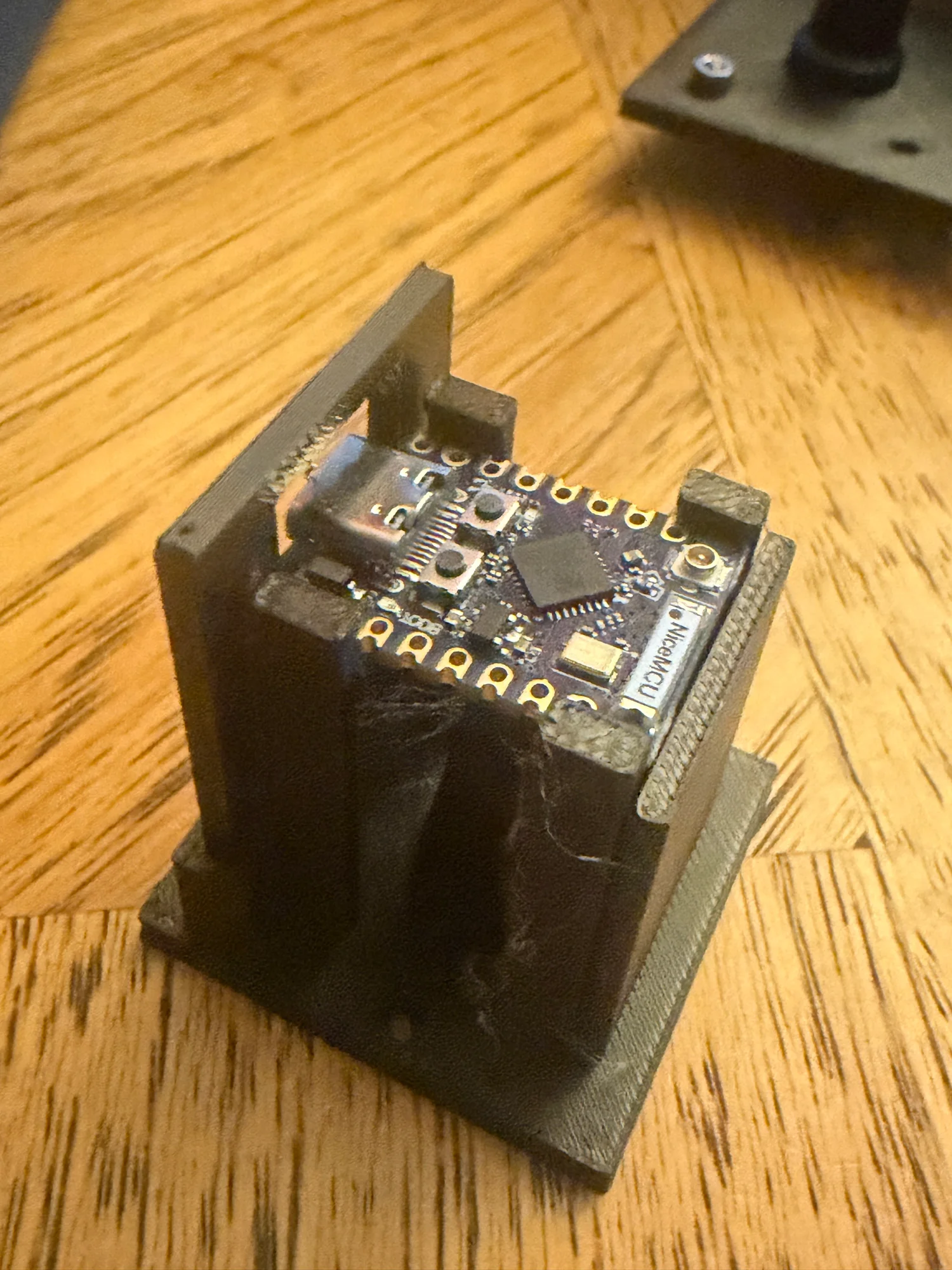 An early fit test. This led to a taller stop behind the board and a smaller USB opening.
We printed small fit samples first. The potentiometer hole and the M3 screw-and-nut holes worked. The potentiometer also has a little metal peg that needs to be captured so the body doesn’t turn with the knob.
And then we managed to put that capture on the wrong side in a later faceplate, despite already having gone through the mirror-image issue in the test part. I printed it, tried to install the potentiometer, and it wouldn’t fit.
That was frustrating. A successful test part doesn’t help much if the geometry gets reversed when it is incorporated into the bigger model.
The enclosure needed to get simpler
The first design had a separate speaker baffle, a knob mount insert, a grille, and a retaining arrangement that was much harder to understand than it needed to be. One of the retaining features came apart when printed. I kept asking how the pieces were actually supposed to connect, because looking at them on the table, it wasn’t obvious.
Eventually I asked to go through it part by part and simplify it.
The current enclosure has three main pieces: one front plate, the middle shell, and the rear cover. The speaker and potentiometer mount to that single front plate. There is a small keeper behind the potentiometer and a separate ESP32 holder on the rear cover.
The front joins the shell with screws through holes in mounting tabs, with nuts accessible from inside before the rear cover goes on. The rear cover screws into plastic pilot holes. I used machine screws and nuts to secure the speaker too.
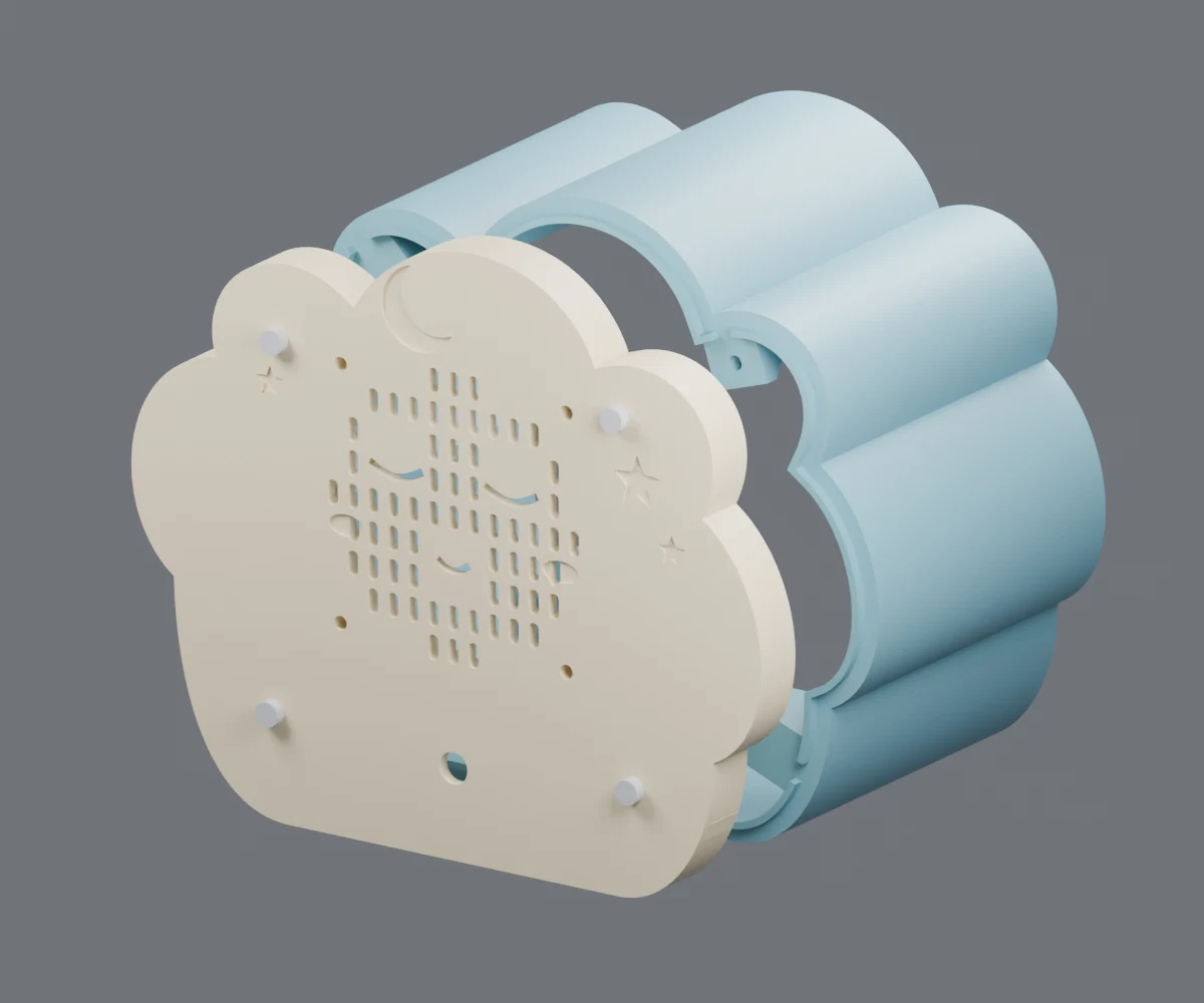 The simplified front-to-shell connection. These are the model’s preview colors.
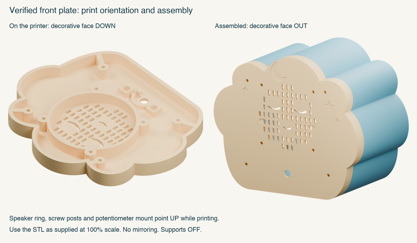 The decorative face prints down. The speaker and potentiometer mounts face into the enclosure. This part cannot simply be flipped to fix an orientation mistake.
We also had to make sure there was actual room to get the ESP32 holder’s mounting nuts into place. A hole through a model isn’t enough if another piece of plastic blocks your access to the nut.
At one point I thought the rear cover didn’t match the cloud shell at all. It did, once I flipped it over. The cloud outline is asymmetric, and I had the inside and outside reversed. That one wasn’t a bad outline, but it was a good reason to be clearer about assembly orientation.
The whole thing is about 165 mm wide, 139 mm tall, and 103 mm deep, so the individual parts fit on the A1 mini. We settled on 2.4 mm outer walls while keeping extra material around the mounting points.
That wall-thickness change saved about 18 grams of filament, but the shell’s estimated print time only went from 4 hours 12 minutes to 3 hours 56 minutes. A lot of discussion for sixteen minutes, but I’ll take the material saving.
The saved slices used a 0.4 mm nozzle, 0.20 mm layers, three walls, 15% infill, and no supports. The shell estimate was 3 h 56 min / 148.6 g and the front plate was 2 h 38 min / 76.4 g. Those are slicer estimates, not stopwatch measurements, and your settings will change them.
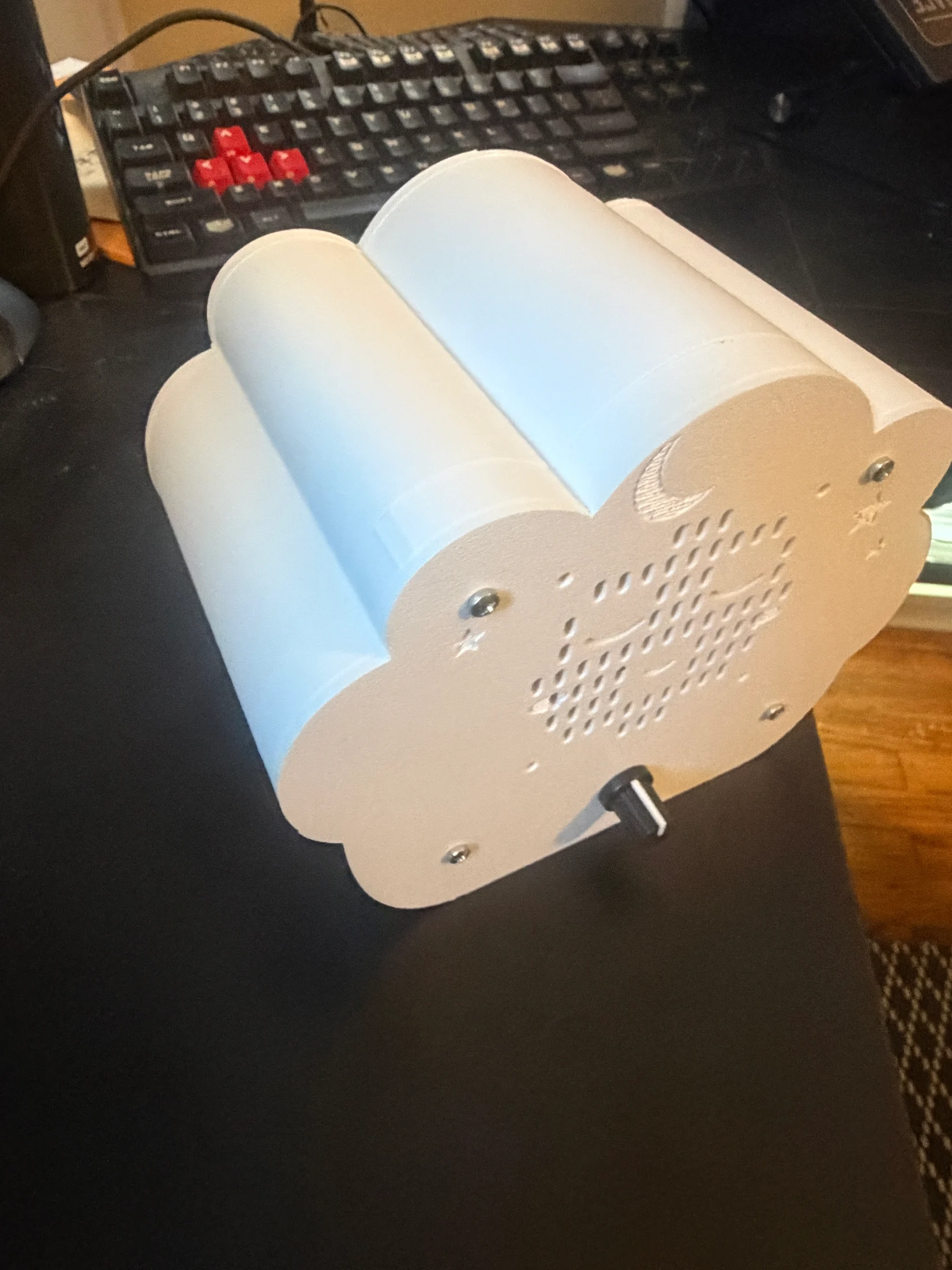
The static was my solder joints
After moving everything off the breadboard and into the enclosure, it started making horrible static. If I jiggled the wiring near the amplifier, sometimes it cleared up.
I suspected the jumper connectors. I swapped wires. I even tried different amplifier boards. It still happened. I was starting to wonder if this was interference, or if all these little square jumper connectors were just terrible.
It was the ESP32 header solder joints.
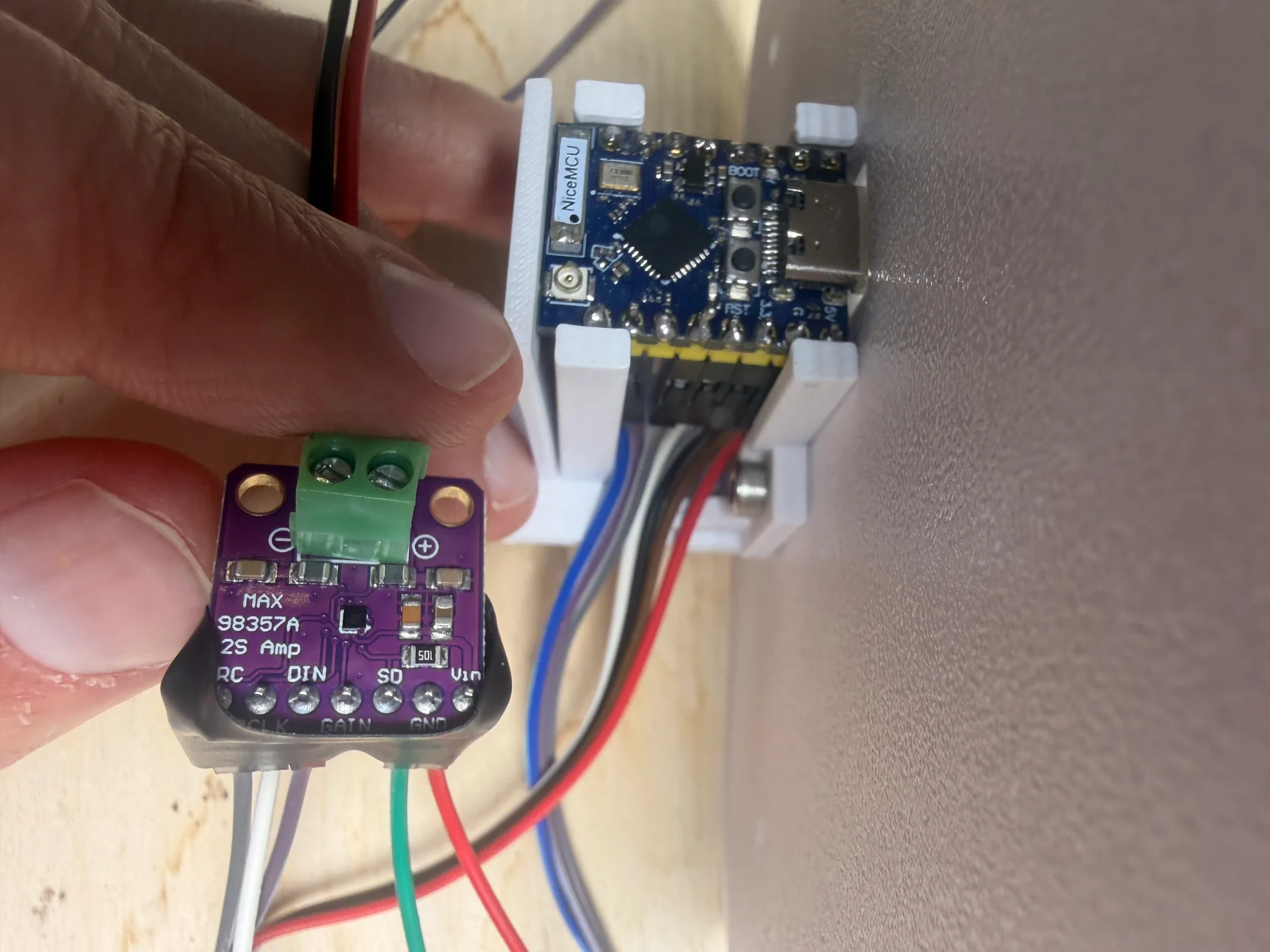
Moving the wiring near the amp was also moving the wiring connected to the ESP32. The place where my hand happened to be wasn’t proof of which component was faulty.
So that is probably the most useful troubleshooting note in this entire post: check the header-to-board joints at both ends before deciding you need new jumper wires, another amplifier, or different firmware. In this case the breadboard working earlier did not mean those joints were good.
Working, with a few things still on the list
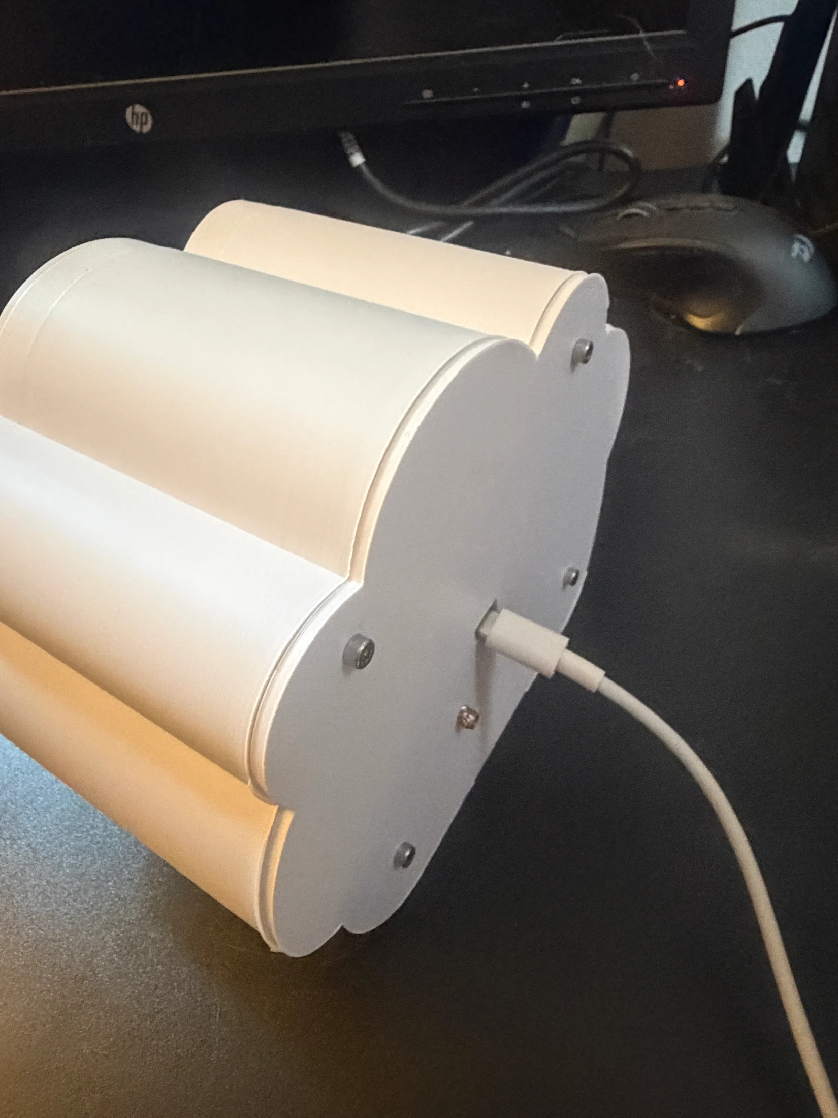
The USB connection still feels a little mushy when I push a cable in. We designed a revised holder with a thicker stop behind the ESP32 and a brace connecting it to the middle support. It keeps the same mounting positions, so it should only require replacing the holder.
I haven’t installed it yet. The model and slice checks passed, but I can’t claim it fixes the feel until I actually print and try it. It is included as an optional revision, with separate print settings and notes.
I might also add a physical button to switch noise modes. Or an HTTP server so I can change modes from a browser instead of plugging it into the computer. Neither of those is in the current firmware.
This was a fun use of the coding agents, and also a pretty good demonstration of where I still needed to be involved. They helped get from an idea to firmware and printable models quickly. They also produced a few things that looked plausible and didn’t work when I tried to put them together. Small fit prints, checking the actual mating surfaces, and being willing to throw out an overcomplicated design mattered a lot.
Anyway, now I have a little cloud ready for when my daughter arrives. It works, I can change the sound, and I have all the files to keep improving it. I’m pretty happy with that.
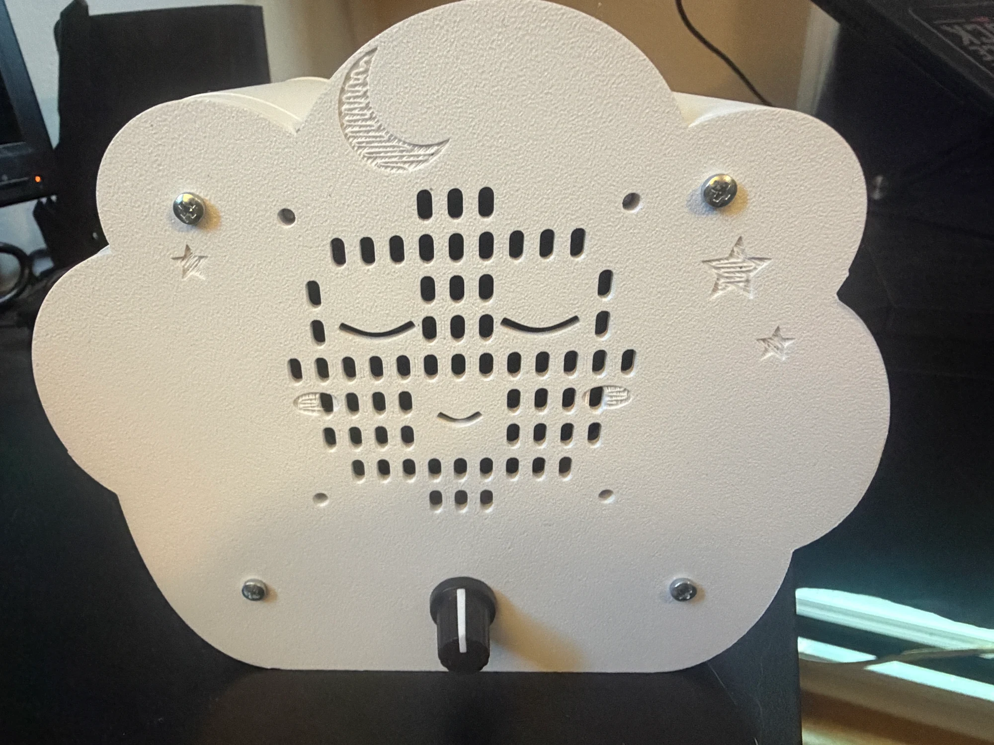
The complete download includes the current build files and photos. Start with its README: it separates the assembled version from the optional, untested holder revision.